How to make the best entry-level Oscilloscope?
01
Introduction
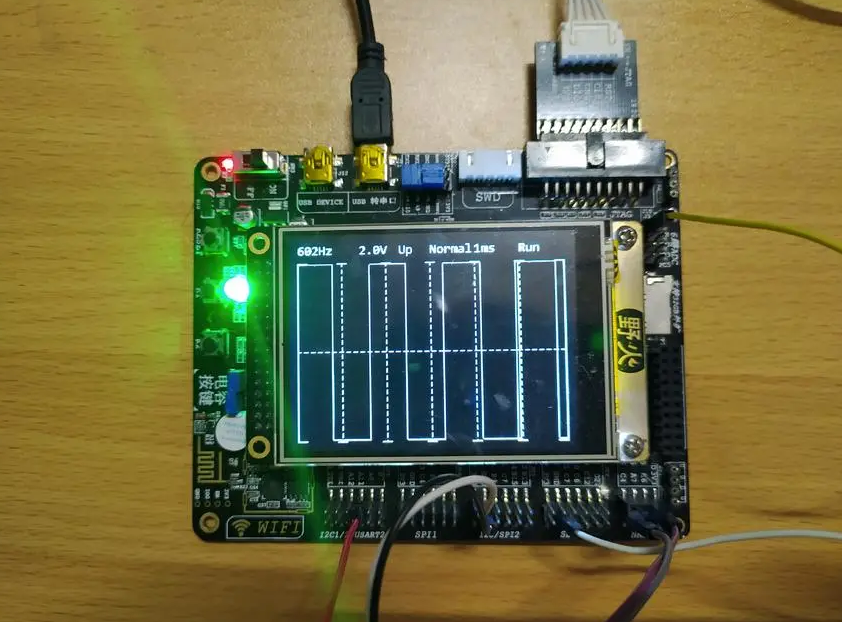
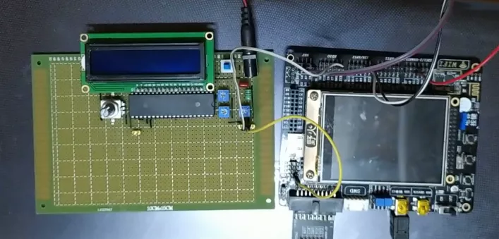
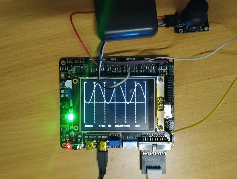
This tutorial documented the steps of creating an Oscilloscope.
Voltage: 0-3.3V,
Frequency: 1Hz-10kHz
3 Sampling Modes: auto, normal and single time
2 Trigger Modes: rising edge and falling edge
02
Development Environment
Hardware:stm32f103, 3.2 inch ILI9341 LCD display
RT-Thread:v3.0.3
IDE:MDK v5.26
03
RT-Thread Inside Part
Kernel: Scheduler, Semaphore, Message Queue.
Scheduler: Create multiple threads for different purposes.
Semaphore: Used to synchronize threads.
Message Queue: Used to transfer the data between threads.
04
Hardware Architecture
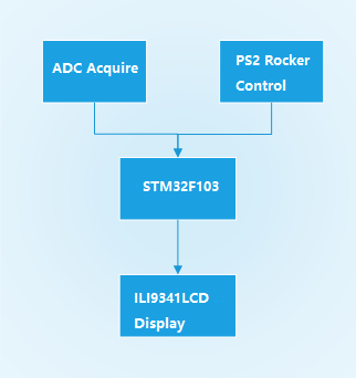
The signal of the waveform generator acquired by the ADC processed on the stm32f103 chip and being displayed on the 3.2-inch ILI9341 LCD screen.
05
Software Architecture
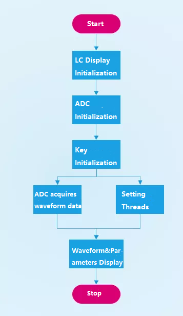
06
Software Module Introduction
Thread:
GetWave_thread:
Wave sampling thread, determine the sampling frequency based on the time represented by each grid of the settings screen, and determine the sampling start point according to the trigger threshold and trigger mode, then sampling the waveform and save it.
PlotWave_thread:
Waveform display thread; Waveforms are displayed according to the area of the screen.
KeyScan_thread:
Key scan thread; Read the key values for conversion and send them to the setting thread.
Setting_thread:
Set the action to execute the thread, perform the settings item modification operation, and refresh the display information.
Message Queue
setting_data_queue:
Read the key scan thread and convert the settings information to the settings thread to change the settings and display the refreshed information.
getwave_status_queue:
Used to communicate between the waveform sampling thread and the waveform display thread to ensure that the sampling waveform is displayed in a timely manner.
key_scan_queue:
Used to communicate between setting threads and key scan threads to ensure that key signals are read in a timely manner while avoiding excessive resource consumption by key scan threads.
07

