Play with GD32303E-EVAL BSP-Read GPS sensor data!
Preparation
This article introduces using the serial drive frame provided by RT-Thread to obtain GPS sensor data and display it in the shell.
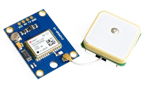
The GPS module model used in this paper is GY-GPS6MV2, which uses the U-BL NEOOX-6M module and is compatible with 3.3V/5V levels.
The GPS module looks like:

The GPS modules have the following pins:

The GPS module and GD32303E-EVAL board are connected as follows:

Development board power supply and connectivity:
Power Supply: The evaluation board uses a Mini USB connector or DC-005 connector to provide a 5V power supply.
Downloader: A JLink or GD-Link tool is required to download the program to the evaluation board.
Serial connection: Connect the PA9 and PA10 pins of evaluation serial 0 using a USB reserect cable and connect to your computer.
Run the test code
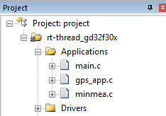
Open the MDK or IAR engineering file and add the attached test code file to the project, as shown in the following image:

Then call the app_init() function in the main function:
\#include


\#include

extern rt_err_t app_init(void);

int main(void)
{
/* user app entry */
if (RT_EOK != app_init())
{
rt_kprintf("app operate failed!\n");
}

return 0;
The app_init()' function first configures the parameters of the serial port to fit the GPS module, and then creates a gps thread in which serial 1 receives the data sent by the GPS module in an interrupt and prints it out.
Running Results
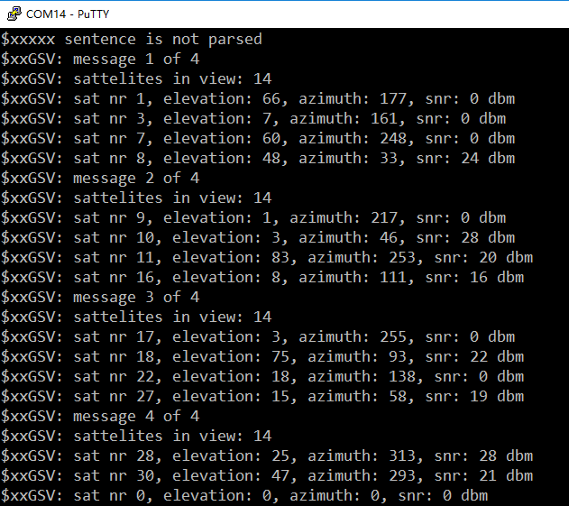
Open the corresponding port on the computer side using putty, the Baud rate is configured to 115200, compile the code and download it to the board, then press reset to restart the board, putty displays the data received from the GPS module.

How to get GPS sensor data using the RT-Thread serial driver?
Using which serial port?
The GD32303E-EVAL BSP has enabled serial 0 (USART0) and serial 1 (USART1) by default, and serial 0 is connected to the USB retring module, so serial 1 can be used to obtain GPS sensor data. Call the rt_device_find()" function, pass in the serial name, find the serial device that the system has registered, and save the serial device handle. The source code is as follows:
\#define GPS_USE_UART "uart1"
/* Serial device handle */
static rt_device_t uart_device = RT_NULL;

/* Look for serial devices in the system */
uart_device = rt_device_find(GPS_USE_UART);

if (RT_NULL == uart_device)
{
rt_kprintf(" find device %s failed!\n",GPS_USE_UART);
return RT_EINVAL;
}
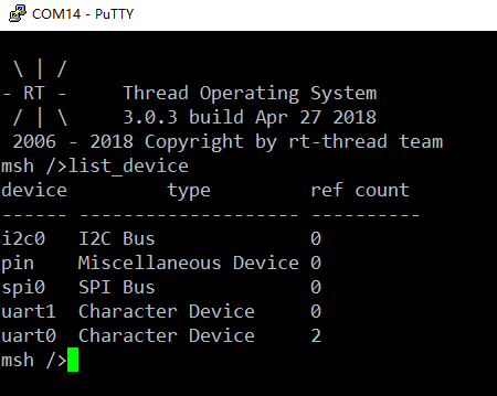
Note: After the system is running, you can view registered devices using list_device command in the shell:

Configure serial transport mode
The serial driver configures the serial port using the default configuration parameters provided by RT-Thread when registering the serial port, and this example requires modifying the baud rate of the serial port and accepting buffer size to fit the GPS module. GPS sends too much data at once, the default configuration of the buffer size is 64 bytes, if the gps thread has not processed the buffer data then the buffer data will be overwritten by new data, resulting in data loss, so when too much data received needs to modify the buffer size. Call the rt_device_control ()) function to configure the serial port.
Note: Changes to the buffer must be completed before the serial port is opened, and changes to the serial transport mode must be made before the serial port can be opened. The source code is as follows:
struct serial_configure gps_use_config =
{
BAUD_RATE_9600, /* 9600 bits/s */
DATA_BITS_8, /* 8 databits */
STOP_BITS_1, /* 1 stopbit */
PARITY_NONE, /* No parity */
BIT_ORDER_LSB, /* LSB first sent */
NRZ_NORMAL, /* Normal mode */
1024, /* Buffer size */
0
};

if (RT_EOK != rt_device_control(uart_device, RT_DEVICE_CTRL_CONFIG,(void *)&gps_use_config))
{
rt_kprintf("uart config failed.\n");
}

if (uart_open(uart_device) != RT_EOK)
{
rt_kprintf("uart open error.\n");
}
if (RT_EOK != rt_device_control(uart_device, RT_DEVICE_CTRL_CONFIG,(void *)&gps_use_config))
{
rt_kprintf("uart config failed.\n");
}
Open Serial Port
Serial port 1 is configured to interrupt the reception of the way to open, call rt_device_open()to open the serial port, the source code is as follows:
/* The serial port receives the event flag */
\#define UART_RX_EVENT (1 << 0)

/* The event control block */
static struct rt_event event;

static rt_err_t uart_open(rt_device_t device)
{
rt_err_t res;

if (device != RT_NULL)
{
res = rt_device_set_rx_indicate(device, uart_intput);
/* Check the return value */
if (res != RT_EOK)
{
rt_kprintf("set %s rx indicate error.%d\n",device->parent.name,res);
return -RT_ERROR;
}

/* Turn on the device in a read-write, interrupted manner */
res = rt_device_open(device, RT_DEVICE_OFLAG_RDWR | RT_DEVICE_FLAG_INT_RX );
/* Check the return value */
if (res != RT_EOK)
{
rt_kprintf("open %s device error.%d\n",device->parent.name,res);
return -RT_ERROR;
}

/* Initialize the event object */
rt_event_init(&event, "event", RT_IPC_FLAG_FIFO);

return RT_EOK;
}
else
{
rt_kprintf("can't open %s device.\n",device->parent.name);
return -RT_ERROR;
}
}
Read serial port date
Serial port 1 executes an interrupt callback letter when it receives data, which sends an event flag that triggers the thread waiting for the event. Call rt_device_read() to read the data, the source code is as follows:
/* Callback function */
static rt_err_t uart_intput(rt_device_t dev, rt_size_t size)
{
/* Send an event */
rt_event_send(&event, UART_RX_EVENT);

return RT_EOK;
}
... ...

static rt_uint8_t uart_getchar(void)
{
rt_uint32_t e;
rt_uint8_t ch;

/* Read 1 byte of data */
while (rt_device_read(uart_device, 0, &ch, 1) != 1)
{
/* Receive an event */
rt_event_recv(&event, UART_RX_EVENT,RT_EVENT_FLAG_AND | RT_EVENT_FLAG_CLEAR,RT_WAITING_FOREVER, &e);
}

return ch;
}
This article provides an overview of the use of RT-Thread serial device interfaces, with more source code reference to the test code. If you need to use other relevant interfaces, please refer to the RT-Thread serial device application notes, to configure the project please refer to the use of ENV tools.

